Chao_Forward

I want to go to the moon. Not because it is easy, but because it is hard.

IMG_0972
IMG_0972
The third generation Robot platform with visual based perception and Visual SLAM algorithms
IMG_0972

repo: https://github.com/forwardkth/chao_robot

Demo:

Hardware platforms:

JetsonTX2 (for advanced algorithms)

Beaglebone White or Black (for vehicle control and sensor interfaces)

Sensors

IntelRealsense D435i

Software platform

ROS kinetic (currently the JetsonTX2 does not support the latest ROS2 version)

To be continue …

This is one example of my work of the object tracking with the fusion of ego positions from both NDT matching pose and GPS signal with Unscented Kalman Filter.

It shows a good stability and real-time performance.

IMG_0972

Red arrow: ego pose from NDT matching
Yellow arrow: GPS ego position
Blue arrow and trajectory: ego positions after UKF

repo: https://github.com/forwardkth/sensor_fusion_apps

This is one of the prototyping project of my team to show the potential benefit of the autonoumous driving bus to simplify and reduce cost for bus scheduling and maintenance at the bus depot.

In the picture below below, you can see me monitoring the system in the bus when it went to the ABB charging station autonomously.

Volov official video:

Description:

I started to build a home sensor network with MySensors solution in 2016.
You can find it here: https://forwardkth.github.io/2015/09/22/mysensors/
Recently I have expanded this project with the Home assistnat server, xiaomi plugs and homeBridge. Now Mysensors platform, xiaomi eco system, Home assistant controller and iOS eco system can be combined together as a complete smart home system.
You can find many similar instruction and tutorials from internet. So I just briefly show some key components needed.

Raspberry Pi based home assistant server:

Home Assistant is an open-source home automation platform running on Python 3. Track and control all devices at home and automate control. Perfect to run on a Raspberry Pi.
https://www.home-assistant.io/


MySensor wireless sensor network:


MySensors is an open source hardware and software community focusing on do-it-yourself home automation and Internet of Things.
It helps people who’d like to create original and affordable sensors and actuators based on components like, Arduino, ESP8266, Raspberry Pi, NRF24L01+ and RFM69.
Website: https://www.mysensors.org/

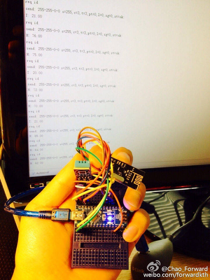
ESP8266 Sensor gateway:

In order to communicate between and collect data from your sensors, we need a wireless communications link. Currently we support a couple of small transceiver called nRF24L01+ and RFM69. You can also run the MySensors library directly on the WiFi enabled ESP8266 for sensors not running on batteries.
It’s pretty smart, small, low-cost and does not consume a lot of battery power.
Gateway - passes data from nodes to your home automation controller as well as from the home automation controller back to nodes. You can attach sensors directly to the gateway as well.
You can also send messages directly between two nodes in the network without transiting through the gateway. For example, your outside temperature sensor can send its data directly to another sensor in your kitchen with an attached display.
It’s possible to build a WIFI enabled gateway running directly on an ESP8266 module. The porting has been done by Yveaux and has been documented here.
https://forum.mysensors.org/topic/1870/esp8266-wifi-gateway-port-for-mysensors
The easiest build option is probably to use the NodeMcu Devkit v.10 (by the NodeMcu Team). This board has the ESP-12 module mounted. Just connect the radio, install gateway software and you’re good to go.

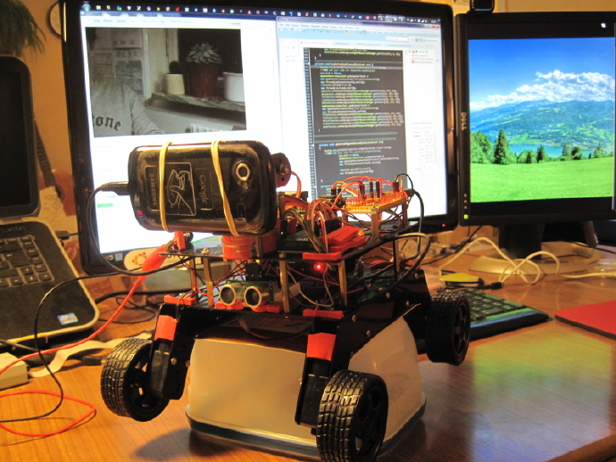
Ardoino Nano sensor nodes:

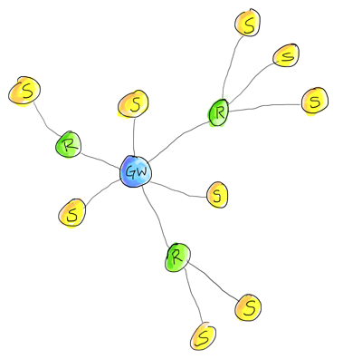
Your sensors will form a tree network topology. Normally the sensor nodes (S) will send their information directly to the gateway (GW). If you live in a mansion or very large house, you may need to enable the repeater mode for some sensor nodes (R) to relay data from sensors that are located far away from the gateway.

Sensor nodes - continuously read the status of all attached sensors and pass the sensor data through the radio network back to the gateway. These puppies have the option to sleep most of the time if you want to run them on battery.

Repeater-sensor nodes - must stay awake in order to pass messages from its child sensor nodes. A repeater-node can optionally include direct-attached sensors and report their sensor data to the gateway. In most setups you will probably not need any repeater-nodes as the transmitter range for the most basic radio is about 20-60 meters.

Each node is assigned a unique sensorId or address that is used for sending and receiving point-to-point messages. You can assign a static sensorId (in the sketch) or let the controller automatically assign one to the sensor. AUTO-mode configures the sensor to request a sensorId from the controller and is the default option for all the examples that we provide. The sensor stores the assigned sensorId in its non-volatile memory to ensure the correct sensorId persists across power transitions. A gateway always has sensorId 0.

The first time a new sensor boots up, it will determine the path to the gateway by sending out a special Help-me-find-my-way-home-message. The repeater-sensor nodes and gateway listen for these messages and will respond to a sensor’s plea-for-help-message. Their reply will inform the sensor how far they are from the gateway so the newly born sensor can determine the shortest path to the gateway, be it directly to the gateway or through a repeater-sensor node which is the closest to the gateway. If the sensor node later loses contact with the gateway or a repeater-sensor node, it will automatically repeat this procedure to determine the best path to the gateway - a sensor node considers contact with the gateway to be lost if it fails to send 3 consecutive messages.

Gateway and repeater-sensor nodes maintain a small routing table to know where to direct their messages to the network surrounding it. The routing table is built up automatically by the repeaters and gateway by introspecting messages received.

A MySensor radio network can consist of up to 254 different radio nodes and each radio node can report data for 254 attached child sensors. This means that you can, in theory, manage data for up to 64516 sensors in a single radio network. If this isn’t enough, you can create another parallel radio network on a different channel and there are 126 available channels [NRF24L01+].

To summarize: New nodes will automatically find the shortest path to gateway and and use a persistent unique sensorId to send and receive point-to-point messages. The tree network is robust and “self heals” as the topology changes. For example, you move a sensor node to a different physical location or a repeater-node dies.

HomeBridge and iOS home automation:

Homebridge is a lightweight NodeJS server you can run on your home network that emulates the iOS HomeKit API.
It supports Plugins, which are community-contributed modules that provide a basic bridge from HomeKit to various 3rd-party APIs provided by manufacturers of “smart home” devices.
This project can be found here: https://github.com/nfarina/homebridge

It is perfect to combine with the HomeAssistant to interact with your home by your iphone home APP and Siri.
Below you can see that homebridge help my iphone detected all my sensor nodes and Xiaomi plugs at home.

Read more »

In order to continue my project (remote contoller for my wifiRobot based on computer vision and sensor fusion), I bought a powerful Desktop PC from HP with the Nvidia Geforce GTX1070 Video Card. It looks quite nice and very easy for maintenance. But I am too old to have interest in playing games. Just use it as a working horse…


It took a lot of time to figure out the solutions for different issues before making the development enviroment ready.

  1. You need to disable the default driver for the video card and install the nvidia one. It is also OK to directly install the CUDA Tookit which has the official driver included.

  2. Disable the secure boot in BIOS. Otherwise the Nvidia driver will not be loaded. And It will not take effect.

  3. It also takes me a lot of time to figure out how to install tensorflow with CUDA9.2.
    actually you need to compile the tensorflow source code with the CUDA9.2 configuration by yourself. this blog might help: http://www.python36.com/install-tensorflow141-gpu/

I installed both the lastest versions of CUDA and CUDNN. But the TensorRT does not support CUDA9.2 for now. Later I will try to install multi versions of CUDA and try to switch among them.


  1. The version of Phython is also a something needs to be noticed. It is very important to know under which version of python the tensorflow is installed. And you need to do corresponding python interpreter configuration in the Pycharm IDE when working with tensorflow

  2. OpenCV is quite easy to install without any issue.

  3. Another thing is that when you compile the Darknet Yolo with Debug = 1, you need to add the following lines in the makefile. Unless the make process will not be successful.

Then I am happy to see the YOLOv3 model can run in more real-time on this PC with maximum 27FPS!
You can see the Video of testing here:

Finally I can really continue my project now: https://github.com/forwardkth/BBRobotController_CV_DL_SF

I will have the both versions of project for Linux and Windows.

Description:

This is a ongoing project. The idea is to build a remote Wifi Robot controller based on OpenCV 3.4.0, cuDNN, CUDA, Deep learning and Sensorfusion.
The sensor data and video are streamed to the PC for computer vision functions and Sensorfusion solutions realization. Then the controller sends back the control command back to the Wifi robot to execute.
You can find it here: https://github.com/forwardkth/BBRobotController_CV_DL_SF
It can be seen as a mini Autonomous Vehicle project with a RaCAM (forward looking Radar and Camera.
I just started to work on this project from time to time since 2017. So the code on Github has not been completed yet.

Historical updates:

2018.5 Project moved to Linux platform
2018.6 Integrate YoloV3 into BBRobot controller project with C++ Wrapper and shared library
BBRobot controller C++ project built up with Eclipse setup

Some tips:
1.in the makefile for generating the shared lib of Darknet, the nvcc configuration should be the path of your local cuda bin folder.

2. Suggest to copy the shared lib to /usr/lib folder to avoid the “can not find xxxx.so” problem.

3. The OpenCV lib dependancies should be manually added to the project build configuration in Eclipse.
4. You can find the Darknet shared lib builder here: https://github.com/forwardkth/DarkLibBuilder

Some old Pictures:


Read more »

以下信息已经过时了,最新的方法可以参考这个链接:

https://blog.ccknbc.cc/posts/how-to-hide-hexo-articles-gracefully/

———之前的———

之前我有一个关于next主题的需求就是希望可以在next主题的主页只显示特定category下的文章。这样就可以在home 首页下控制想要突出展示的文章。
比如我的博客下混合了技术类和生活类文章,我可以选择只在首页展示技术类的,而其他类别的文章不会在首页列出,但是可以到category里面点击查看。
这样就不用像以前的老博客那样开两个博客再链接了。
https://github.com/iissnan/hexo-theme-next/issues/843
具体做法如下:

Read more »

I made a simple iOS App as the remote UI controller UI of my WifiRobot last week. It is simple and not looks so nice. I will try to make it better later.
The communication is based on TCP protocol. I am considering to build it like a general App for all kinds of Wifi Robot projects.
You can do the commands configurations and modify the video streaming address to fit your robot design.

There is a demo video below:
youtube:

Read more »


Filco Ninja Majestouch-2 Tenkeyless Tactile Action UK Keyboard

I bought this mechanical keyboard from the UK website ‘thekeyboardcompany’. I received the package today. It is a very nice programmer keyboard with high quality. I am very satisfied with it.

In the beginning, I don’t know which swtich I should choose, especially the brown switch or the blue switch. Frankly speaking I prefer the blue switch. Because I hear the type sound from youtube. The blue one let you type faster and feel more clear. But considering the noise and other people around you, finally I chose the brown switch one. This is also recommanded by a google engineer. Another good thing I like this keyboard is the front face printing design. I have an old logitec keyboard. All the printing characters are gone or not clear after five years’use. The new keyboard overcomes this problem completely by priting nothing on the top. That is clever. The only thing is that it is a little expensive. It cost me 1700 SEK. But the similer keyboard from the same OEM producer only cost you half. I think between 600 SEK to 800 SEK can be a reasonable price.

Anyway I like this keyboard and feel happy when typing my code under linux. (by the way, it takes about 5 mins to start to work after I plugged in the usb cable… Before that,I thought this keyboard did not support linux system)

The following links are the excellent libraries you can use for the beaglebone development. Pybbio is based on Python. Libbulldog is for java. And BlackLib employs the power of C++. Maybe Lua in the future?

It seems like the script languages are more and more popular for the embedded system. I think it will be more easier as the embedded platform is more and more powerful. I would like to try all the following three libs on my beaglebone robot and compare the performances. My robot is using Pybbio. And i am working with BlackLib now.

pybbio
libbulldog
BlackLib

Read more »


This project is my second master degree thesis work at KTH, Sweden between 2010 and 2011.
The aim of this thesis project is to develop a novel current sensor probe which is low cost, light weight, and easy to be integrated in power component (compact in size, without complex insulation and relative high safety level). The bandwidth should be from DC to KHz. It should fulfill the requirements of current harmonics measurements of DC transmission system as well as the capacity of direct current measurement with acceptable response time, precision, sensitivity and accuracy.

Background

Current measurement has been and is still one of the key aspects in power systems. In the traditional High Voltage (HV) and Extra High Voltage (EHV) grid, the current measurements are realized by current transformers - CTs. These are usually a separate unit for the CT function and for each phase. The cost is considerable and these measurements are therefore made only where strongly needed. Bad reliability of the transformer will impact directly on the system: an insulation failure of a CT will make parallel components unable to operate until repaired. The traditional CTs also need careful consideration of saturation limits during fault conditions. The CTs connect to the instrumentation, signal capturing and display equipment by direct galvanic connection, with all the EMC (electromagnetic compatibility) problems of induced voltages from electromagnetic fields, and risks if the CT insulation breaks down.
High current and current harmonics are also very critical parameters for the power quality monitoring, harmonics suppression and control & protection mechanism in high voltage direct current transmission systems. The current sensor most commonly used is the Rogowski coil. But the traditional Rogowski coil is not very sensitive to low frequency current. And it is impossible for direct current measurement. In recent years, the all fiber OCT (Optical Current Transformer) which is based on the optical Faraday Effect began to be used. But it is too expensive and highly complex to be widely used in power systems at the present stage.
Therefore there is a need of HV (High Voltage) current sensor that has a wider frequency bandwidth as well as the capacity of measuring DC (Direct Current). Meanwhile this kind of current sensor should have the features like low cost, light weight, and easy to be integrated in to the power systems (compact in size, easy installation and relative high safety level).

Abstract

High current and current harmonics are very critical parameters used for the power quality monitoring, harmonics suppression as well as control and protection function in high voltage direct current transmission system. Rogowski coil is one of the most common current sensors used in power system. But the traditional Rogowski coil is not sensitive to low frequency current. It is impossible to be used for direct current measurement. In recent years, the all fiber OCT (Optical Current Transformer) which is based on the optical Faraday Effect is applied. But it is too expensive and highly complex to be widely deployed in power systems at the present stage. Therefore there is a need of developing a high current sensor with a wider frequency bandwidth as well as the capacity of measuring direct current. Meanwhile this kind of current sensor should include the features like low cost, light weight, and easy to be integrated into the power systems (compact in size, easy installation and relative high safety level).
This thesis report presents an approach with the capacity of both high DC current measurement and high AC current measurement by using a novel hybrid current sensor probe which is the combination of the PCB based Rogowski coils, GMR (Giant Magneto Resistance) sensor and the principle HOKA. The Lab experiments have shown a qualified performance. It is capable to capture the current of 220 Amps from DC up to 250 KHz with the sensitivity about 0.002 V/A (DC), acceptable linearity and accuracy within ±1%.
This novel hybrid current sensor is very suitable for the direct high current measurement as well as the current harmonics measurement in the DC power transmission systems.


Description:

This is my second generation Tele-operation robot built since 2015. This robot is based on the open source platform Beaglebone white which running with Debian Linux.

The Beaglebone is a credit-card-sized Linux computer that connects to the Internet and runs software such as Android 4.0 and Ubuntu with plenty of I/O and processing power for real-time analysis provided by an AM335x 720MHz ARM® processor. It has 256M DDR2 RAM, 3D graphics accelerator, power management capacity.

All of these above makes it an excellent platform for building sensor based embedded systems and Robotics.

The source code on github: https://github.com/forwardkth/BBRobot

Historical Project Updates:

2015

  1. Modification to the class BalckPWM
  2. Add Servo motor control class “BlackServo”
  3. Add Servo control demo code under /BlackLib/examples folder
  4. Add demo WiFi robot code (example_wifirobot.h) as a example under /BlackLib/examples folder
  5. Add Video streaming code

2016

  1. New remote control UI with C sharp and WPF
  2. iOS APP for WiFi Robot remote control

2017

  1. Start working with the Computer Vision based remote controller for the WiFiRobot (ongoing…)

2018

  1. Add formal WiFi robot project code under “BBRobot/WiFiRobot/“
  2. Add Json support for Multiple sensor data transmission

DEMO videos:

The Demo video 2018

The Old DEMO video in 2015 summer on Youtube: (The performance now is much better than it is shown in the video. There are new demo videos in 2016 below.)

The new DEMO video in 2016 on Youtube:

DEMO video in Youku: (For Visitors from China...)

you can see more by clicking Read more below :)

Read more »

Description:

This is my first generation Tele-operation robot built during 2014. Now I have already had my second generation robot with pure Linux OS. But the first one is still a interesting try.

The old google Nexus android phone is used as the controller as well as wireless communication module.&ensp The IOIO-OTG Open source board is employed to be the interface between android OS and other devices. Another Experimental board EXP F5438 with TI MSP430 F5438 mcu is connected with the IOIO board through RX/TX.

Maybe you have question like “this MSP430 board is not needed or not necessary”. Yes, you are right. The IOIO board is enough for basic GPIOs, PWM control and so on. But this robot is my experimental platform.
It means that I would like to construct it as complex as this in order to do more experiments and explore more possibilities.

The EXP F5438 board running uCOS II real-time operation system does all the real-time control job e.g motor control, sensor data capture, control other executer.
And the Android phone can focus its work on video, audio streaming, data communication, receiving orders from my laptop. On my laptop I write a GUI with JAVA as control terminal which communicate through WIFI with my Anroid controller APP.

The whole structure is not difficult to understand. But as we known, more complex the system is, the more problem will happen. you will never know them until you actually debug it.

you can see more pictures and DEMO videos by clicking read more below :)

Read more »

Overview:

The basic idea of this project is to develop a kind of ECG monitoring and analysis system. It includes a handheld ECG recording device, a data gateway, mobile phone application, web application (GUI) and a stationary which used to do the interaction between the patients and the doctors. The patients can monitor their ECG condition any time and upload the data via bluetooth and internet to the remote database for the analysis by the doctors later. The doctors can give the feedback to the patients via the web application or Phone application.

I together with my team were responsible for the development of the Cardio Device which is based on MSP430experimental board “WASA” and a bluetooth module from “Bluegiga”.


The data transmiting among Cardio device, PC and mobilephone.

Read more »

Description:

Imaging the situation in a museum, some antiques are put inside a hermetically sealed container. We want to monitor the temperature and moisture inside. But we donot hope to open it. This small device can give us a solution. The device can be put inside the sealed container and capture the temperature and moisture information. We can read the sensor data from outside of the container with a RFID reader without open it. But We know that the passive RFID tags can only send fixed information (ID) when it gets energy from the RFID reader. Then the reader can recognize and identify the specific tag. How can we read the dynamic data from a passive RFID?

In this project a passive RFID tag’s coil loop is cut off and connected with the MSP430 experimental board. We use the processor’s GPIO to control the connection or disconnection of the loop in order to modulate the active information.

Then a communication protocol is created for the data transmition between the reader and the sensing device. First of all, the same communication bit rate is defined both in the device and the reader which is 50 bits per second. Then the protocol defines that the reader receives binary 1 when it can detect the tag ID, otherwise means binary 0. The protocol also defines that the data package sent to the reader includes start sign 9bits, data 32 bits and end sign 9 bits. So the sending rate of the device and the receiving rate of the reader are synchronized. The sensing device detects the temperature and moisture info and encodes the sensor data into a 50 bits binary package according to the protocol. Then it will modulate this data package with the RFID tag’s connection and disconnection. The RFID reader (antena) is connected to SUSE linux computer through serial port. A program running on the PC is responsible to control the reader and translate the 50 bits data package received into temperature info and humidity info.

0%